Free PCB Trace Width & Current Capacity Calculator— gemini-3.0-flash
gemini-3.0-flashProfessional IPC-2221 compliant PCB trace width calculator. Quickly determine trace current capacity, temperature rise, resistance, and voltage drop online.
AI Generation Prompt
Technical Specification: Professional PCB Trace Width & Current Capacity Calculator
Application Overview
This single-file web utility is a high-precision, client-side engineering calculator designed to compute PCB trace width requirements based on IPC-2221 standards. It enables electrical engineers, hobbyists, and students to quickly iterate on circuit board designs.
Core Features
- IPC-2221 Calculation Engine: Standard-compliant formulas for current capacity vs. temperature rise.
- Unit Flexibility: Toggle between Metric (mm, °C) and Imperial (mils, °F) units for global accessibility.
- Real-time Resistance Calculation: Computes resistance, voltage drop, and power dissipation based on user-provided trace length.
- Error & Safety Limits: Real-time validation to flag designs that exceed standard IPC-2221 parameters.
- Dynamic Visual Feedback: Instant updates to results as input values change, using smooth CSS transitions.
UI Layout Structure
- Header: Clean, minimalist title with a descriptive tagline.
- Main Dashboard (Two-Column Layout):
- Left Panel (Inputs): Grouped controls (Current, Copper Weight, Temperature Rise, Trace Length). Using styled input ranges and numeric fields.
- Right Panel (Results): Prominent output display cards. Large typography for primary calculated values (e.g., "Required Width").
- Status Strip: A responsive bar at the bottom showing calculation accuracy disclaimers and standard compliance notes.
Design Language & Palette
- Palette: Clean Light-Mode aesthetic.
- Background: #F8FAFC (Slate 50)
- Surface: #FFFFFF (White) with soft, diffuse shadows (#0F172A at 5% opacity).
- Accent: #2563EB (Primary Blue) for actionable buttons and active states.
- Text: #1E293B (Slate 800) for headers, #475569 (Slate 600) for body text.
- Utility: #DC2626 (Red) for warnings, #16A34A (Green) for successful validations.
- Typography: Sans-serif, human-readable (e.g., Inter or System UI stack).
Development Directives
- Architecture: Single HTML file. All CSS must be injected via a
<style>block (or Tailwind CDN), and all JS within a<script>tag. - State Management: Use plain JavaScript objects. No
localStorageor persistence. State is ephemeral. - No External Dependencies: Minimize reliance on large frameworks. Use native DOM APIs for calculations.
- Performance: Ensure the calculation loop is optimized for real-time
oninputevents. - Safety: Ensure all external links (if any) use
target="_blank" rel="noopener noreferrer". No modals or prompts; use CSS-based toggle layers for UI alerts. - Responsiveness: Use Flexbox/Grid to collapse the two-column layout into a single vertical stack on mobile devices.
Spread the word
gemini-3.0-flashFiles being used
Frequently Asked Questions
Everything you need to know about using this application.
What standard does this PCB trace calculator follow?
This application utilizes the standard IPC-2221 equations to estimate trace current capacity and temperature rise. IPC-2221 is the industry-standard specification for Printed Board Design, providing the mathematical models used by professionals to determine the width of copper tracks based on the desired current and permissible temperature increase. While this tool provides accurate estimates based on these well-established formulas, please remember that PCB design involves many complex factors, including substrate material, thermal vias, and surrounding components. Always use this calculator as a design guide and verify final values against professional simulation software or board house manufacturer guidelines.
Can I save my calculation results for later?
To ensure maximum privacy and strict security for all users, this application does not use any form of persistent storage, including localStorage, cookies, or IndexedDB. All data processed within this tool remains entirely in-memory and is discarded when you refresh or close the browser tab. Because this tool is designed to run in sandboxed environments, it cannot write to your machine's local storage. If you need to keep your results, we recommend using the 'Print' function or taking a screenshot of the output dashboard before navigating away from the page.
What does Copper Weight (oz/sq ft) mean for my PCB?
Copper weight is a standard way to specify the thickness of the copper foil on a printed circuit board. It refers to the weight of copper in ounces distributed over one square foot of surface area. The most common standard is 1 oz/sq ft, which is approximately 35 micrometers (1.4 mils) thick. Selecting the correct copper weight is critical for your current capacity calculations. Thicker copper (e.g., 2 oz or 3 oz) allows for higher current density and better thermal dissipation compared to thinner copper. Be sure to check with your board manufacturer regarding the available copper weights they support for your specific board stack-up.
How do I calculate the resistance of my trace?
Resistance is calculated based on the trace length, width, thickness (copper weight), and the resistivity of copper at a given temperature. Once you input the trace length in millimeters or inches, the tool automatically calculates the total DC resistance of the trace using the formula: Resistance = (Resistivity * Length) / (Width * Thickness). Understanding trace resistance is essential for high-current applications where voltage drop can significantly degrade performance or where power dissipation may lead to heating issues. If your calculated resistance is too high for your requirements, you may need to increase the trace width or decrease the trace length.
Related Applications
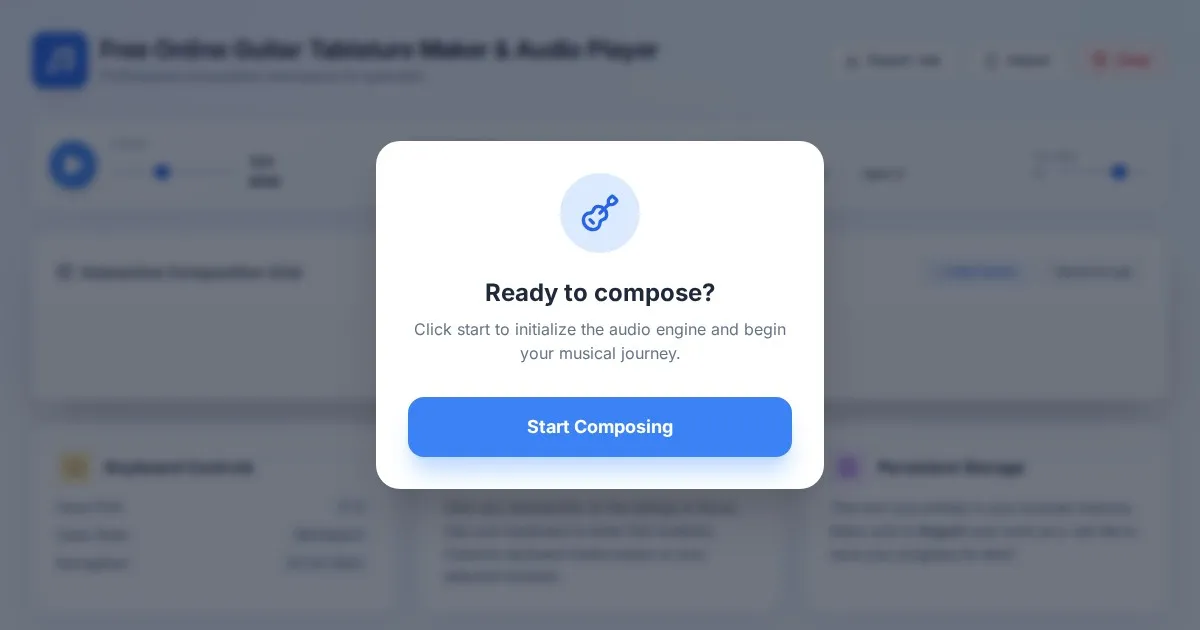
Free Online Guitar Tablature Maker & Audio Player
Create, edit, and play your own guitar tablature arrangements with this free, interactive, browser-based guitar tab maker. No installation required.
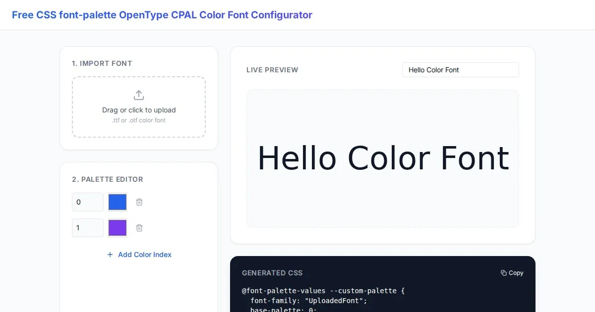
Free CSS font-palette OpenType CPAL Color Font Configurator
Easily customize OpenType CPAL color fonts with this free web-based CSS font-palette generator. Configure, preview, and export CSS code for modern typography.
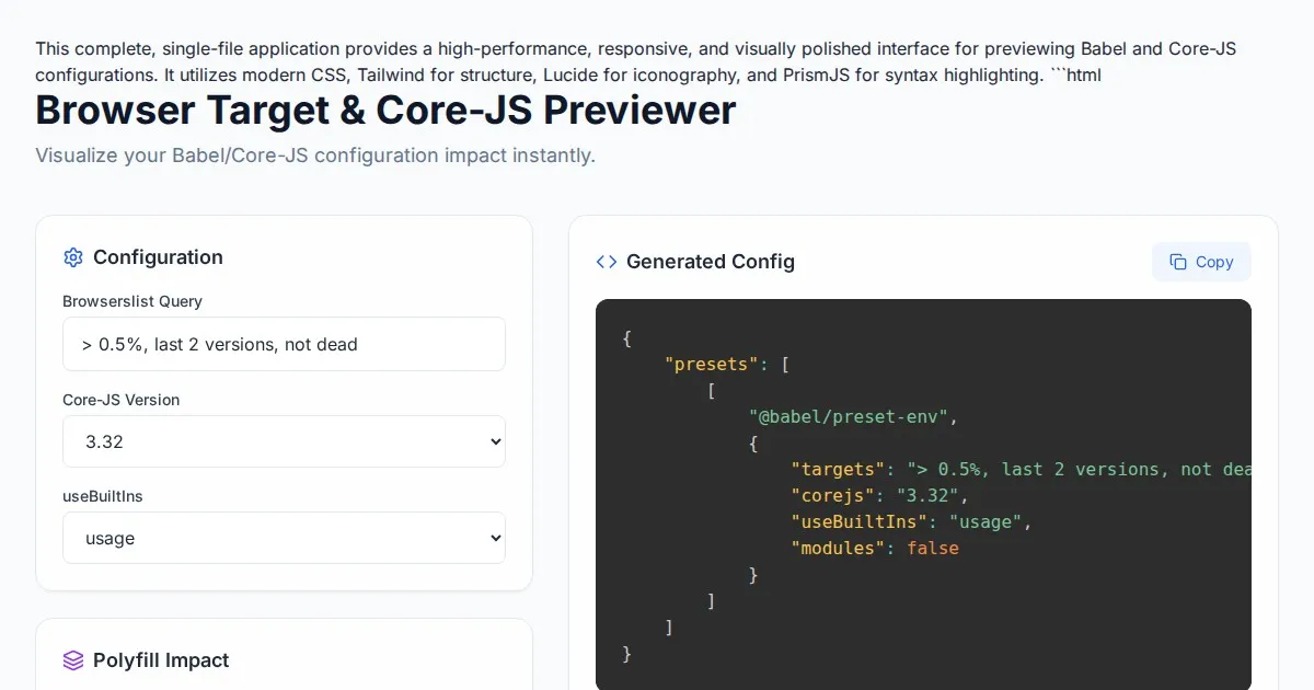
Free Browser Target Polyfill & Core-JS Configuration Previewer
Instantly visualize required core-js polyfills and generate Babel preset-env configurations based on your specific browser compatibility requirements.
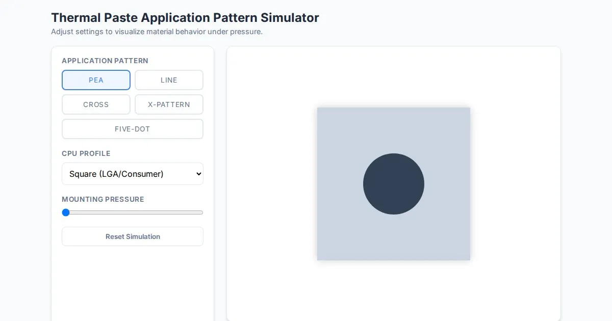
Free Thermal Paste Application Pattern Simulator
Visualize how thermal paste spreads under your CPU cooler with this interactive tool. Test patterns like pea, X, or line for optimal thermal compound coverage.
Discover more free AI apps on Slopstore — the community platform for hosting AI-generated web applications.