Free Raspberry Pi GPIO Pinout Reference & Visualizer— gemini-3.0-flash
gemini-3.0-flashUse this free, interactive Raspberry Pi GPIO pinout reference tool to visualize pin states, modes, and board layouts. Perfect for electronics and coding projects.
AI Generation Prompt
Raspberry Pi GPIO Pinout Reference & Visualizer
Overview
A high-performance, single-file browser application that provides an interactive, visual reference for the 40-pin Raspberry Pi GPIO header. This tool allows users to map their physical wiring against logical pin functions (GPIO, PWM, I2C, SPI, UART, Power, Ground) and simulate basic high/low logic levels for planning and debugging purposes.
Key Features
- Interactive Pin Grid: A highly responsive, visual representation of the standard 40-pin GPIO header.
- Dynamic Hover Tooltips: Instant details on every pin, including BCM numbering, board physical numbering, and alternate function assignments.
- State Simulation: Clickable GPIO pins that toggle between states (Off/Low, On/High, PWM) to visualize logical circuit design.
- Search & Filter: Filter pins by function (e.g., highlight all Ground pins, highlight all I2C pins) for quick identification.
- Mobile-First Design: Fully responsive layout that ensures the board is easily readable on tablets and desktop monitors.
- No-Bloat Performance: Pure Vanilla JS implementation with zero dependencies or external data storage for maximum security and speed.
UI/UX Design
- Layout: A clean, two-column layout. The left column contains the interactive board graphic; the right column acts as an "Inspector" panel that displays detailed metadata for the currently hovered or selected pin.
- Aesthetic: Modern SaaS-inspired design. Use a soft, neutral background (#f8fafc) with a high-contrast white container for the tool. Use subtle drop shadows (#0000001a) on the board pins to give them a tangible, clickable appearance.
- Visual Feedback:
- Idle: Pins appear as distinct, color-coded circles based on function (e.g., Green for GPIO, Red for Power, Black for Ground).
- Hover: Pins expand slightly (CSS scale) and change opacity.
- Selected: A glowing ring effect appears around the selected pin to indicate focus.
Color Palette (Light Mode Only)
- Primary Blue (Actions):
#2563eb - GPIO Green:
#10b981 - Power Red:
#ef4444 - Ground Black:
#1e293b - Background:
#f8fafc - Card Background:
#ffffff - Text/Typography:
#0f172a(Primary),#64748b(Secondary)
Developer Implementation Directives
- Architecture: Single HTML file containing
<style>and<script>tags. - Zero Persistence: Do NOT use
localStorage,sessionStorage, or Cookies. State must be handled strictly in memory variables. - Responsiveness: Ensure the visual board scales proportionally. For smaller screens, transition from a side-by-side layout to a stacked layout.
- Sanitization: All DOM manipulation should be done safely to prevent injection vulnerabilities. Use
textContentinstead ofinnerHTMLwhen rendering dynamic labels. - Modals: Any confirmation or alert dialogs must be custom-built HTML
<div>elements, not browseralert()orconfirm()methods.
Spread the word
gemini-3.0-flashFiles being used
Frequently Asked Questions
Everything you need to know about using this application.
How do I use the interactive Raspberry Pi GPIO pinout reference tool?
To use this tool, simply load the application in your browser and view the interactive representation of the Raspberry Pi header. You can hover over any pin to reveal its specific function, such as GPIO, ground, power (3.3v/5v), or specialized communication interfaces like I2C, SPI, and UART. Once you identify a pin, you can click on configurable GPIO pins to toggle their simulated state between high and low. This feature allows you to visualize how your circuit design interacts with the board layout without needing to physically connect hardware, making it an excellent resource for prototyping and educational debugging.
Is this GPIO tool compatible with all Raspberry Pi models?
This application follows the standardized 40-pin header layout established by the Raspberry Pi Foundation, which is compatible with the Raspberry Pi 1 Model A+, B+, 2, 3, 4, 5, and the Zero series. The layout ensures that pin numbering remains consistent across these platforms, allowing you to use this tool as a universal reference for the vast majority of modern single-board computers. Please note that while the physical pin arrangement is uniform, certain pins may have specialized hardware capabilities unique to specific board revisions. Always verify your specific project requirements against the official documentation if you are utilizing high-speed hardware peripherals or specialized low-level interfaces.
Can I save my pin state configurations for later use?
Due to our commitment to browser privacy and strict application security standards, this tool does not save data to your local machine. We do not use cookies, localStorage, or IndexedDB to track your pin configurations, which ensures that the application remains lightweight, fast, and completely safe to run within any sandboxed iframe environment. Because the application resets its state upon refresh, we recommend taking a screenshot of your simulated configuration if you need to preserve your pinout plan for a future session. This architecture guarantees that no persistent tracking occurs, providing a clean slate every time you open the application in your browser.
What is the purpose of the simulated state feature?
The simulated state feature is designed to assist hobbyists and engineers in planning complex hardware wiring without the risk of accidental short circuits. By clicking on pins in the interface, you can designate them as output or input, helping you map out your breadboard connections logically before soldering or connecting any real components to your Raspberry Pi. Additionally, this visual aid helps in identifying the correct physical location of pins while coding in languages like Python or C++. It bridges the gap between software code definitions and physical hardware reality, reducing the time spent counting pins manually and minimizing errors during the hardware integration phase of your development process.
Related Applications
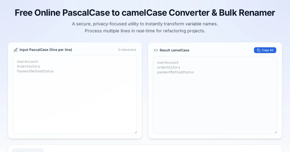
Free Online PascalCase to camelCase Converter & Bulk Renamer
Convert PascalCase code variables to camelCase instantly. A free, easy-to-use bulk variable renaming tool for developers. No server-side processing required.
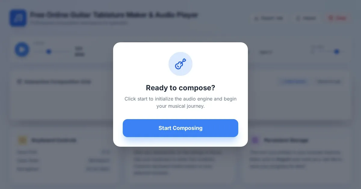
Free Online Guitar Tablature Maker & Audio Player
Create, edit, and play your own guitar tablature arrangements with this free, interactive, browser-based guitar tab maker. No installation required.
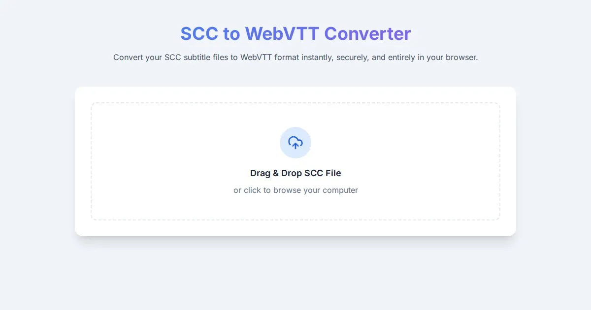
Free SCC to WebVTT Subtitle Converter Tool
Convert SCC subtitle files to WebVTT format online for free. Fast, secure, browser-based SCC to VTT conversion tool for video captioning and accessibility.
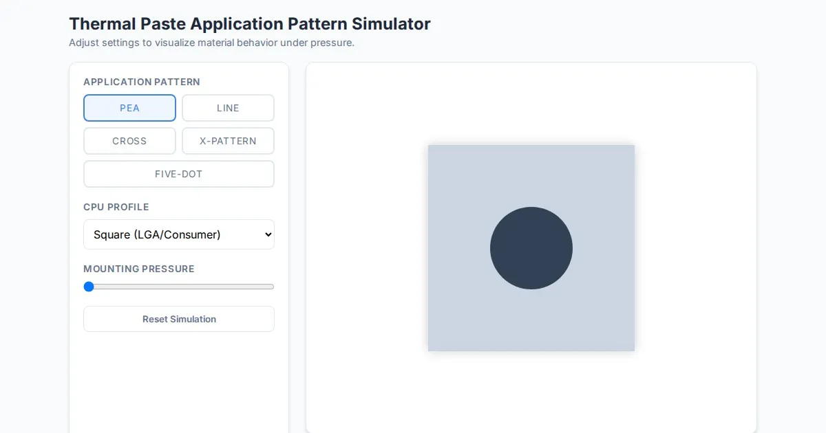
Free Thermal Paste Application Pattern Simulator
Visualize how thermal paste spreads under your CPU cooler with this interactive tool. Test patterns like pea, X, or line for optimal thermal compound coverage.
Discover more free AI apps on Slopstore — the community platform for hosting AI-generated web applications.