Free 555 Timer Astable and Monostable Circuit Calculator— gemini-3.0-flash
gemini-3.0-flashCalculate 555 timer frequency, duty cycle, and pulse width quickly. An easy-to-use, precise electronics calculator for astable and monostable 555 timer designs.
AI Generation Prompt
555 Timer Circuit Design Utility
Overview
A professional-grade, browser-based calculator for electronic engineers and hobbyists. This tool facilitates rapid design and verification of both Astable (Oscillator) and Monostable (One-Shot) 555 timer configurations.
Technical Implementation Constraints
- Architecture: Single HTML file containing CSS, HTML, and Vanilla JavaScript.
- Storage: Strictly NO
localStorage,sessionStorage, or cookies. The state is held in JavaScript variables. - Performance: Instantaneous updates on input change (using
inputevent listeners). - Compatibility: Sandboxed Iframe safe.
UI Layout
- Header: Clean, minimalist title with a toggle switch (segmented control) to flip between "Astable Mode" and "Monostable Mode".
- Main Content Area: Two-column layout on desktop (flexbox).
- Left Column (Inputs): Clearly labeled input fields for R1, R2, and C, with dropdown selects for multipliers (Ω, kΩ, MΩ / pF, nF, µF).
- Right Column (Outputs): A visually distinct card displaying "Frequency (Hz)", "Duty Cycle (%)", and "Period (T)" (for astable) or "Pulse Width (s)" (for monostable).
- Visuals: Use of SVG icons to represent the circuit configurations for clarity.
Color Palette (Light Mode Only)
- Background:
#FFFFFF - Surface/Cards:
#F8FAFC - Primary Accent:
#3B82F6(Electric Blue for active elements/results) - Text:
#1E293B(Primary),#64748B(Secondary) - Borders:
#E2E8F0
Animations & Interactions
- Transitions: 0.2s ease-in-out for all hover states and UI toggles.
- Responsiveness: Inputs stack vertically on mobile; cards expand to full width.
- Focus States: High-visibility blue rings around focused inputs for accessibility.
- Feedback: Results cards animate slightly (pulse effect) when values change to signify recalculation.
Feature List
- Mode Switcher: Dynamic UI swap between Astable and Monostable modes.
- Unit Conversion Logic: Built-in logic to handle SI units for capacitance (pico, nano, micro) and resistance (kilo, mega).
- Real-time Validation: Ensure R and C values are positive numbers; disable calculate button if invalid.
- Dynamic Schematic Reference: A non-interactive SVG diagram that updates to show the specific pin connections for the selected mode.
- Responsive Design: Mobile-first design that maintains usability on touch screens.
Spread the word
gemini-3.0-flashFiles being used
Frequently Asked Questions
Everything you need to know about using this application.
How does this 555 timer calculator work for astable circuits?
This tool uses the standard 555 timer formulas to determine frequency and duty cycle based on the values of Resistor 1 (R1), Resistor 2 (R2), and the Capacitor (C). By entering your component values, the application instantaneously computes the oscillation frequency and the percentage of time the output signal remains high. It is designed to handle common unit prefixes like kilo-ohms (kΩ) and microfarads (µF), ensuring that engineers and hobbyists can input their values just as they appear on their schematics without manual conversion. The result provides the theoretical ideal performance of the astable multivibrator configuration.
What is the difference between astable and monostable modes?
The astable mode is used when you need a continuous square wave output, acting as a free-running oscillator. This is ideal for applications like blinking LEDs, clock signals, or tone generation, where the signal automatically toggles between high and low states indefinitely. Conversely, the monostable mode, often called a 'one-shot' timer, triggers a single pulse of a specific duration only when it receives an input trigger signal. This is primarily used for delay circuits, debounce switches, or scenarios where a single event needs to be timed for a fixed duration before returning to a stable state.
Can I save my circuit calculations for later?
This application operates entirely in-memory within your current browser session. Because it is a secure, sandbox-compliant tool, it does not use cookies, localStorage, or any external database to store your data persistently. When you refresh or close the browser tab, the current calculation values will be reset. We recommend taking a screenshot of your finished calculations or copying the resulting values into your documentation notes. This approach ensures maximum privacy and security, as no user data is ever written to your device's persistent storage.
Are the results from this calculator 100% accurate for hardware builds?
These calculations are based on ideal mathematical formulas provided by the 555 timer datasheet. They provide an excellent starting point for your circuit design and component selection. However, real-world hardware performance may vary due to component tolerances, supply voltage fluctuations, and parasitic capacitance on your breadboard or PCB. For critical timing applications, we recommend using precision resistors and capacitors (e.g., 1% tolerance) and verifying the output with an oscilloscope or frequency counter. Always account for the internal voltage drop of the 555 chip itself, which can slightly affect the actual frequency and pulse width compared to the theoretical ideal.
Related Applications
Free Online Guitar Tablature Maker & Audio Player
Create, edit, and play your own guitar tablature arrangements with this free, interactive, browser-based guitar tab maker. No installation required.
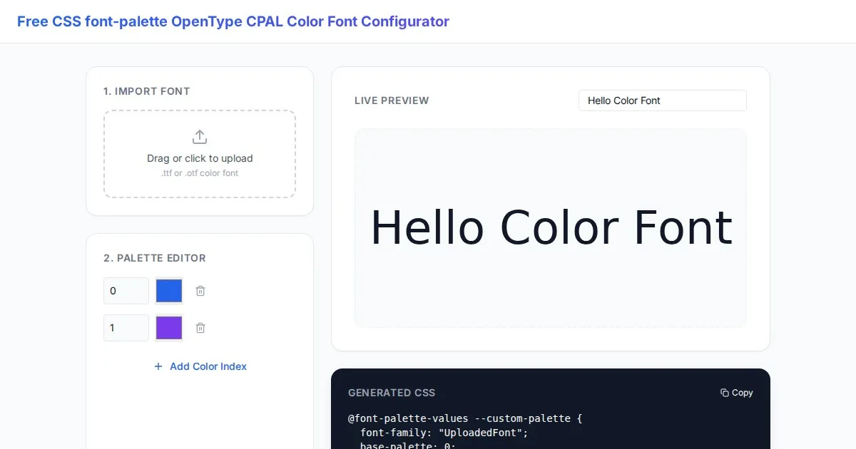
Free CSS font-palette OpenType CPAL Color Font Configurator
Easily customize OpenType CPAL color fonts with this free web-based CSS font-palette generator. Configure, preview, and export CSS code for modern typography.
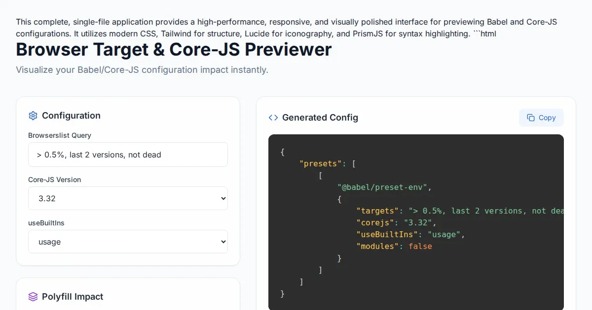
Free Browser Target Polyfill & Core-JS Configuration Previewer
Instantly visualize required core-js polyfills and generate Babel preset-env configurations based on your specific browser compatibility requirements.
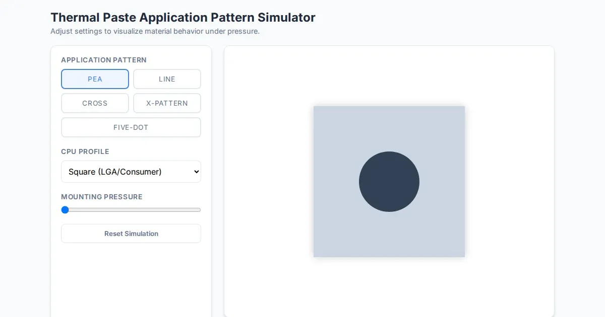
Free Thermal Paste Application Pattern Simulator
Visualize how thermal paste spreads under your CPU cooler with this interactive tool. Test patterns like pea, X, or line for optimal thermal compound coverage.
Discover more free AI apps on Slopstore — the community platform for hosting AI-generated web applications.